Thursday 27 October 2016

Installing Foreman on CentOS 7 / Debian 8

Foreman provides a feature rich frontend for Puppet - that allows you to easily deploy, manage and monitor your puppet infrastructure.

Note: It is highly recommended that you use the official Puppet packages from the official Puppet repository when using t in conjunction with Foreman.

So - lets firstly add the Foreman repository with:

yum install epel-release http://yum.theforeman.org/releases/1.7/el7/x86_64/foreman-release.rpm

yum -y install foreman-installer

or for Debian 8:

echo "deb http://deb.theforeman.org/ jessie 1.13" > /etc/apt/sources.list.d/foreman.list
echo "deb http://deb.theforeman.org/ plugins 1.13" >> /etc/apt/sources.list.d/foreman.list
apt-get -y install ca-certificates
wget -q https://deb.theforeman.org/pubkey.gpg -O- | apt-key add -

apt-get update && apt-get -y install foreman-installer

and then run the installer with:

foreman-installer

I got a few errors during the initial install:

"Error: Removing mount files: /etc/puppet/files does not exist"

and

'Error executing SQL; psql returned pid 1842 exit 1: 'ERROR:  invalid locale name: "en_US.utf8"'

In order to resolve the above problem we should generate en_US.utf8 locale - in Debian we run:

dpkg-reconfigure locales

and ensure 'en_US.utf8' is selected.

Uninstall foreman with:

sudo apt-get --purge remove foreman foreman-installer foreman-proxy
sudo rm -rf /var/lib/foreman /usr/share/foreman /usr/share/foreman-proxy/logs
sudo rm -R /etc/apache2/conf.d/foreman*

and attempt to reinstall:

foreman-installer

Review the logs at /var/log/foreman/install.log for any problems:

cat /var/log/foreman/install.log | grep ERROR

and launch the web app:

https://hostname

The defualt login details are supposedly: admin / changeme - but this didn't seem to be the case for myself - so I ended up manually resetting the password in the console with:

foreman-rake permissions:reset

Initially we will want to import all of our puppet classes - this can be performed by going to:

Configure >> Classes and then click on 'Import classes from puppet.xyz.com'

Tuesday 25 October 2016

Locking down a linux system with the help of Puppet

Puppet as well as a great deployment tool is brilliant for ensuring that your systems configuration is as it should be.

When working with Linux (well any operating system really) I like to create a security baseline that acts as an applied standard accross the organization.

I am going to base the core configuration (while ensuring that the configuration is compatible with the vast majority of Linux distributions.):

puppet module install hardening-ssh_hardening
puppet module install hardening-os_hardening
puppet module install puppetlabs-accounts
puppet module install puppetlabs-ntp
puppet module install puppetlabs-firewall
puppet module install saz-sudo

vi /etc/puppet/modules/accounts/manifests/init.pp

import "/etc/puppet/modules/firewall/manifests/pre.pp"
import "/etc/puppet/modules/firewall/manifests/post.pp"

node default {

  ########### Replace firewalld with IPTables ############
  package { tcpdump: ensure => installed; }
  package { nano: ensure => installed; }
  package { wget: ensure => installed; }
  package { firewalld: ensure => absent; }

  service { 'firewalld':
    ensure     => stopped,
    enable     => false,
    hasstatus  => true,
  }

  service { 'iptables':
    ensure     => running,
    enable     => true,
    hasstatus  => true,
  }

  ########### Configure firewall ###########
  resources { "firewall":
    purge   => true
  }

  Firewall {
    before  => Class['fw::post'],
    require => Class['fw::pre'],
  }

  class { ['fw::pre', 'fw::post']: }
 
}

Note: We can generate the password hash with:

makepasswd --clearfrom=- --crypt-md5

We can now apply our host specific configuration:

import "/etc/puppet/manifests/nodes.pp"

and in our nodes.pp file we will define our settings for the induvidual hosts:

vi /etc/puppet/manifests/nodes.pp

node 'hostname.domain.com' {

  include privileges

  ########### Custom Firewall Rules ###########
  firewall { '100 Allow inbound access to tcp/8000':
  dport     => 8000,
  proto    => tcp,
  action   => accept,
  }
 
  firewall { '101 Allow inbound access to tcp/80':
  dport     => 80,
  proto    => tcp,
  action   => accept,
  }

  ########### Configure Groups ###########
  group { 'admins':
   ensure => 'present',
   gid    => '501',
        }
     
  ########### Configure NTP ###########
  class { 'ntp':
    servers => ['0.uk.pool.ntp.org','1.uk.pool.ntp.org','2.uk.pool.ntp.org','3.uk.pool.ntp.org']
  }
 
  ########### Configure OS Hardening ###########
  class { 'os_hardening':
    enable_ipv4_forwarding => true,
  }
 
  ########### Configure User Accounts ############
  accounts::user { 'youruser':
  ensure => "present",
  uid      => 500,
  shell    => '/bin/bash',
  password => '$11234567890987654.',
  locked   => false,
  groups   => [admins],
  }
 
  ########### SSH Hardening #############
  class { 'ssh_hardening::server': }

  ########### Configure SSH Keys #############
  ssh_authorized_key { 'user@domain.com':
  user => 'youruser',
  type => 'ssh-rsa',
  key  => '345kj345kl34j534k5j345k34j5kl345[...]',
}

}

We need to create a new module to handle sudo for us:

mkdir -p /etc/puppet/modules/privileges/manifests && cd /etc/puppet/modules/privileges/manifests

vi init.pp

class privileges {
   user { 'root':
     ensure   => present,
     password => '$1$54j534h5j345345',
     shell    => '/bin/bash',
     uid      => '0',
   }

   sudo::conf { 'admins':
     ensure  => present,
     content => '%admin ALL=(ALL) ALL',
   }

   sudo::conf { 'wheel':
     ensure  => present,
     content => '%wheel ALL=(ALL) ALL',
   }
}

And make sure our include statement is present in our nodes.pp file.

we should also create our firewall manifiests:

vi /etc/puppet/modules/firewall/manifests/pre.pp

class fw::pre {

  Firewall {
    require => undef,
  }

  # basic in/out
  firewall { "000 accept all icmp":
    chain    => 'INPUT',
    proto    => 'icmp',
    action   => 'accept',
  }

  firewall { '001 accept all to lo interface':
    chain    => 'INPUT',
    proto    => 'all',
    iniface  => 'lo',
    action   => 'accept',
  }

  firewall { '006 Allow inbound SSH':
    dport     => 22,
    proto    => tcp,
    action   => accept,
  }

  firewall { '003 accept related established rules':
    chain    => 'INPUT',
    proto    => 'all',
    state    => ['RELATED', 'ESTABLISHED'],
    action   => 'accept',
  }

  firewall { '004 accept related established rules':
    chain    => 'OUTPUT',
    proto    => 'all',
    state    => ['RELATED', 'ESTABLISHED'],
    action   => 'accept',
  }

  firewall { '005 allow all outgoing traffic':
    chain    => 'OUTPUT',
    state    => ['NEW','RELATED','ESTABLISHED'],
    proto    => 'all',
    action   => 'accept',
  }

}

vi /etc/puppet/modules/firewall/manifests/post.pp

class fw::post {

  firewall { '900 log dropped input chain':
    chain      => 'INPUT',
    jump       => 'LOG',
    log_level  => '6',
    log_prefix => '[IPTABLES INPUT] dropped ',
    proto      => 'all',
    before     => undef,
  }

  firewall { '900 log dropped forward chain':
    chain      => 'FORWARD',
    jump       => 'LOG',
    log_level  => '6',
    log_prefix => '[IPTABLES FORWARD] dropped ',
    proto      => 'all',
    before     => undef,
  }

  firewall { '900 log dropped output chain':
    chain      => 'OUTPUT',
    jump       => 'LOG',
    log_level  => '6',
    log_prefix => '[IPTABLES OUTPUT] dropped ',
    proto      => 'all',
    before     => undef,
  }

  firewall { "910 deny all other input requests":
    chain      => 'INPUT',
    action     => 'drop',
    proto      => 'all',
    before     => undef,
  }

  firewall { "910 deny all other forward requests":
    chain      => 'FORWARD',
    action     => 'drop',
    proto      => 'all',
    before     => undef,
  }

  firewall { "910 deny all other output requests":
    chain      => 'OUTPUT',
    action     => 'drop',
    proto      => 'all',
    before     => undef,
  }

}

Ensure all of our mainifests are valid:

puppet parser validate site.pp

Sources: https://docs.puppet.com/pe/latest/quick_start_sudo.html
https://www.linode.com/docs/applications/puppet/install-and-configure-puppet

Monday 24 October 2016

Quickstart: Installing and configuring puppet on CentOS 7 / RHEL

For the puppet master we will need a VM with at least 8GB of RAM, 80GB of disk and 2 vCPU.

The topology will comprise of two nodes - MASTERNODE (The puppet server) and the CLIENTNODE (the puppet client).

Firstly we should ensure that NTP is configured on both the client and server.

We'll now install the official Puppet repository:

sudo rpm -Uvh https://yum.puppetlabs.com/puppet5/puppet5-release-el-7.noarch.rpm
yum install puppetserver puppetdb puppetdb-termini
sudo systemctl enable puppet
sudo systemctl start puppetserver

We should then set our DNS name etc. for the puppet server - append / change the following in vi /etc/puppetlabs/puppet/puppet.conf:

[main]
certname = puppetmaster01.example.com
server = puppetmaster01.example.com
environment = production
runinterval = 1h
strict_variables = true

[master]
dns_alt_names = puppetmaster01,puppetdb,puppet,puppet.example.com
reports = puppetdb
storeconfigs_backend = puppetdb
storeconfigs = true
environment_timeout = unlimited

We will also need to ensure the PuppetDB service is started - although we'll firstly need to install / setup PostgreSQL before we proceed - follow the guidance here  - however stop just before the 'user creation' and instead see below:

sudo -u postgres sh
createuser -DRSP puppetdb
createdb -E UTF8 -O puppetdb puppetdb
exit

and ensure the pg_trgm extension is installed:

sudo -u postgres sh
psql puppetdb -c 'create extension pg_trgm'
exit

Restart postgres and ensure you can login:

sudo service postgresql restart
psql -h localhost puppetdb puppetdb
\q

And define the database connection details here:

vi /etc/puppetlabs/puppetdb/conf.d/database.ini

Replacing / adding the following directives:

[database]
classname = org.postgresql.Driver
subprotocol = postgresql
subname = //127.0.0.1:5432/puppetdb
username = puppetdb
password = <yourpassword>

Note: Also ensure that you are using PostgreSQL version >=9.6 otherwise the puppetdb service will fail to start. (as the epel release is at current only on 9.2) Uninstall the existing postgres install and install the newer version with: yum install postgresql-96 postgresql-server-96 postgresql-contrib-96

Important: By default the puppet master will attempt to connect ot PuppetDB via the hostname 'puppetdb' - however we can change this behaviour by defining the following on the puppet master:

vi /etc/puppetlabs/puppet/puppetdb.conf

and adding:

[main]
server_urls = https://puppetmaster01.example.com:8081

sudo service puppetdb start

Configure ssl support with:

sudo puppetdb ssl-setup

Now either use puppet to start and ensure that the db service runs on boot with:

sudo puppet resource service puppetdb ensure=running enable=true

or

sudo systemctl enable puppetdb
sudo systemctl start puppetdb

We will proceed by generating the server certificates:

export PATH=/opt/puppetlabs/bin:$PATH
sudo puppet master --verbose --no-daemonize

Once you see 'Notice: Starting Puppet master version 5.2.0' pres Ctrl + C to escape.

We can review certificates that have been created by issuing:

sudo puppet cert list -all

and start the puppet master:

sudo service puppet start

We'll also need to add an exception in for TCP/8140 and TCP/8081 (PuppetDB) (for clients to communicate with the puppet master):

sudo iptables -I INPUT 3 -i eth0 -p tcp -m state  --state NEW,ESTABLISHED -m tcp --dport 8140 -j ACCEPT
sudo iptables -I INPUT 3 -i eth0 -p tcp -m state  --state NEW,ESTABLISHED -m tcp --dport 8081 -j ACCEPT

sudo iptables-save > /etc/sysconfig/iptables

Puppet Client Installation


we should then install our client:

sudo rpm -Uvh https://yum.puppetlabs.com/puppet5/puppet5-release-el-7.noarch.rpm
sudo yum install puppet
sudo systemctl enable puppet

edit puppet.conf:

[main]
certname = agent01.example.com
server = puppetmaster01.example.com
environment = production
runinterval = 1h

and restart the puppet client:

systemctl restart puppet

Set path details:

export PATH=/opt/puppetlabs/bin:$PATH

The puppet server (master) utilizes PKI to ensure authenticity between itself and the client - so we must firstly generate a certificate signing request from the client:

puppet agent --enable
puppet agent -t

At this point I got an an error:

Error: Could not request certificate: Error 400 on SERVER: The environment must be purely alphanumeric, not 'puppet-ca'
Exiting; failed to retrieve certificate and waitforcert is disabled

This turned out due to a version mismatch between the puppet client and server.

Note: The Puppet server version must always be >= than that of the puppet client - I actually ended up removing the official puppet repo from the client and using the EPEL repo instead.

and then attempt to enable puppet and generate our certificate:

puppet agent --enable
puppet agent -t

At this point I got the following error:

Exiting; no certificate found and waitforcert is disabled.

This is because the generated certificate has not yet been approved by the puppet master!

In order to approve the certificate - on the puppet master issue:

puppet cert list

and then sign it by issuing:

puppet cert sign hostname.domain.com

We can then view the signed certificate with:

puppet cert list -all

Now head back to the client and attempt to initialise the puppet agent again:

puppet agent -t

However again - I got the following message:

Could not retrieve catalog from remote server: Error 500 on SERVER

Note: Using the following command allows you to run the puppet server in the foreground and provided a lot of help when debugging the above errors:

puppet master --no-daemonize --debug

We should (if everything goes to plan) see something like:

Info: Retrieving pluginfacts
Info: Retrieving plugin
Info: Caching catalog for puppetmaster.yourdomain.com
Info: Applying configuration version '1234567890'
Info: Creating state file /var/lib/puppet/state/state.yaml
Notice: Finished catalog run in 0.02 seconds

We want to install few modules firstly:

puppet module install ghoneycutt/ssh

We will extend our modules:

vi /etc/puppet/modules/firewall/manifests/ssh.pp

ssh::permit_root_login
  permit_root_login => 'no',

Now lets create our manifest:

vi /etc/puppetlabs/code/environments/production/manifests/site.pp

import "/opt/puppetlabs/puppet/modules/firewall/manifests/*.pp"

node default {

  package { tcpdump: ensure => installed; }
  package { nano: ensure => installed; }
  package { iptables-services: ensure => installed; }
  package { firewalld: ensure => absent; }

  service { 'firewalld':
    ensure     => stopped,
    enable     => false,
    hasstatus  => true,
  }

  service { 'iptables':
    ensure     => running,
    enable     => true,
    hasstatus  => true,
  }

  resources { "firewall":
    purge   => true
  }

  include common
  include ssh


We should also validate the file as follows:

sudo puppet parser validate site.pp

The puppet client (by default) will poll every 30 minutes - we can change this by defining:

runinterval=900

Where 900 is == number of seconds. (This should be appended to the 'main' section in puppet.conf

We can also test the config by issuing:

puppet agent --test

Wednesday 19 October 2016

Retrieving the top requesting hosts from the nginx access logs

We will fristly inspect the log format:

tail -f /var/log/nginx/access.log.1

89.248.160.154 - - [18/Oct/2016:21:58:38 +0000] "GET //MyAdmin/scripts/setup.php HTTP/1.1" 301 178 "-" "-"
89.248.160.154 - - [18/Oct/2016:21:58:38 +0000] "GET //myadmin/scripts/setup.php HTTP/1.1" 301 178 "-" "-"

Fortunately apache has a standardized format so we can parse the logs pretty easily - we will firstly use a regex to extract the requester IP from the log file (note the '^' is present to ensure we don't pickup the IP anywhere else e.g. the requested URL.):

grep -o '^[0-9]\{1,3\}\.[0-9]\{1,3\}\.[0-9]\{1,3\}\.[0-9]\{1,3\}' /var/log/nginx/access.log.1

We then want to remove any duplicates so we are presented with unique hosts and ideally sort these:

grep -o '^[0-9]\{1,3\}\.[0-9]\{1,3\}\.[0-9]\{1,3\}\.[0-9]\{1,3\}' /var/log/nginx/access.log.1 | uniq | sort

Now we can use a while loop to retrieve the results:

#!/bin/bash

input='/var/log/nginx/access.log.1'

grep -o '^[0-9]\{1,3\}\.[0-9]\{1,3\}\.[0-9]\{1,3\}\.[0-9]\{1,3\}' $input | uniq | sort | while read -r line ; do

count=$(grep -o $line $input | wc -l)

echo "Result for: " $line is $count

done


But you might only want the top 5 requesters - so we can expand the script as follows:


#!/bin/bash

input='/var/log/nginx/access.log.1'

grep -o '^[0-9]\{1,3\}\.[0-9]\{1,3\}\.[0-9]\{1,3\}\.[0-9]\{1,3\}' $input | uniq | sort | while read -r line ; do

count=$(grep -o $line $input | wc -l)

# Bash creates a subshell since we are piping data - so variables within the loop will not be available outside the loop.

echo $count for $line >> temp.output

done

echo "Reading file..."

for i in `seq 1 5`; do

cat temp.output | sort -nr | sed -n $i'p'

done

# cleanup
rm -f temp.output

Tuesday 18 October 2016

Customer - ISP BGP Lab (Removing private ASN's)

For this lab we will have a customer site (ASN 16500) that connects to an ISP over over BGP.

The customer has an inner core consisting of 3 routers (R1, R2 and R3) running OSPF as an IGP. The customer's edge has a border router that is running BGP and will peer with the ISP's router R5.

The goal here is to ensure that when clients within the core network attempt to access the internet - will be directed towards are edge router and in turn the IPS's edge router (R5.)


The GNS3 lab can be downloaded here.

The process flow is as follows:

1. Client in customer core (e.g. 172.16.0.200) attempts to ping a public IP: 8.0.0.1

2. R1 is hooked up to the OSPF backbone and is aware of a default route being advertised on R4. R2 also has a default route pointing to R5 (which is not part of the OSPF domain, rather BGP.)

3. R4 is advertising a public (BGP) prefix of 14.0.0.0/24 - so in order to make sure any packets originating from our internal subnet (172.16.0.0/23) are reachable by the remote subnets we should NAT the traffic to the 14.0.0.0/24 subnet.

4. Once NAT'd R4 will lookup the appropriate root for 8.0.0.1 in it's routing table - although we will configure prefix filtering - so R4 will only see a default route to R5.

5. Once the packet arrives at R5 the route will be looked up against the routing table and it will identify that 8.0.0.0/24 is within ASN 500 and will forward the packet out lo0.

Since we are connecting to a private ASN from the customer to ISP we will have to remove the private AS when it hits the IPS's public ASN / router.

R1>
enable
conf t

int e0/0
ip address 192.168.10.1 255.255.255.252
no shutdown
ip ospf 1 area 0

int e0/1
ip address 192.168.20.1 255.255.255.252
no shutdown
ip ospf 1 area 0

int lo 0
ip address 172.16.0.1 255.255.254.0

router ospf 1
network 172.16.0.0 0.0.1.255 area 0

Note: At this point I expected the loopback adapter subnet to be advertised via OSPF - well it was - but only as a /32 (rather than /24)... It turns out by default the router treats the address as a single IP e.g. /32 even if you have defined something other than /32 - in order to instruct the router to advertise its actual subnet we can issue:

int lo 0
ip ospf network point-to-point
do clear ip ospf pro

R2>
enable
conf t

int e0/0
ip address 192.168.20.2 255.255.255.252
no shutdown
ip ospf 1 area 0

int e0/1
ip add 192.168.30.1 255.255.255.252
no shutdown
ip ospf  1 area 0

int e0/2
ip add 192.168.40.2 255.255.255.252
no shutdown
ip ospf 1 area 0

R3>
enable
conf t

int e0/0
ip address 192.168.10.2 255.255.255.252
no shutdown
ip ospf 1 area 0

int e0/1
ip address 192.168.30.2 255.255.255.252
no shutdown
ip ospf 1 area 0

R4>
enable
conf t

int e0/0
ip address 192.168.40.1 255.255.255.252
no shutdown
ip ospf 1 area 0

int e0/1
ip address 192.178.50.1 255.255.255.252
no shutdown

Ensure that we do not advertise anything over our link to the ISP:

router ospf 1
passive-interface e0/1

Check neighbor adjacencies etc. with:

do show ip ospf ne

and

do show ip route [ospf]

Now we will setup eBGP between R4 and R5:

R4>
router bgp 16000
neighbor 14.0.0.2 remote-as 16001

R5>
enable
conf t

int e0/0
ip address 14.0.0.1 255.255.255.0
no shutdown

router bgp 16001
neighbor 14.0.0.1 remote-as 16000
network 14.0.0.0 mask 255.255.255.0

we want the customers edge router to use the ISP's edge router as the default gateway - so in order to this we need to use the 'defualt-originate' command:

R5>
neighbor 14.0.0.1 default-originate

We also want to ensure that R4 is not flooded with prefixes when its hooked up to BGP - so we can configure a prefix list to filter out all routes accept the default route R5 is advertising:

R5>
ip prefix-list default-route seq 5 permit 0.0.0.0/0
router bgp 16001
neighbor 14.0.0.1 prefix-list default-route out

This will instruct the ISP's router (R5) to inject a default route into the BGP table for the R4 peer (only).

R5>
int e0/1
ip address 192.168.60.2 255.255.255.252
no shutdown

router bgp 16001
neighbor 192.168.60.1 remote-as 500

Now review the routing table on R4 and confirm that only the default route is present:

do show ip route

R6>
int e0/0
ip address 192.168.60.1 255.255.255.252
no shutdown

int lo 0
ip address 8.0.0.1 255.255.255.0

router bgp 500
neighbor 192.168.60.2 remote-as 16001

We also want to ensure that the traffic is NAT'd to 14.0.0.0 or else return traffic from the remote subnets will not reach us (since they are unaware of our internal subnets as they are not present in our BGP table.):

R4>
int e0/0
ip nat inside

int e0/1
ip nat outside

ip access-list standard NAT
permit 172.16.0.0 0.0.1.255
ip nat inside source list NAT interface e0/1 overload

We can then attempt to ping 8.0.0.1 from R1 (source address 172.16.0.1):

R1>
do ping 8.0.0.1 source 172.16.0.1

You should see a new translation in the NAT table:

R4>
do show ip nat trans

Now lets setup R6 and configure BGP:

R6>
int e0/1
ip address 192.168.70.2 255.255.255.252
no shutdown

router bgp 500
neighbor 192.168.70.1 remote-as 600

R7>
int e0/0
ip address 192.168.70.1 255.255.255.252
no shutdown

router bgp 600
neighbor 192.168.70.2 remote-as 500

Also note that the ISP in this scenario is using a private ASN to peer with the customer - the traffic's next hop will be ASN 500 which is reversed for public use and hence we will need to ensure that the private AS number is removed before before it forwards the prefix to other public AS's. To do this we will apply the 'remove-private-as' command:

R6>
router bgp 500
neighbor 192.168.70.1 remove-private-as
do clear ip bgp *

and then check the 14.0.0.0/24 prefix in our BGP table:

do show ip bgp 14.0.0.0/24

and we should notice that the AS_PATH now only contains ASN 500.

Monday 17 October 2016

Tip: Debugging with 'debug ip packet'

The 'debug ip packet' command is a brilliant way to help diagnose problems with traffic traversing the router - although there are a few drawbacks - one being that only packets that are switched using process switching (i.e. switched with the help of the CPU) will be visible in the 'debug ip packet' output - other switching mechanisms like Fast Switching and CEF will not.

Although we can use the 'no ip route-cache' within interface mode to force packets to be switched with process switching - although note that this can have an adverse affect on the CPU is busy environments and should only be used if absolutely necessary.
int gi0/0
no ip route-cache
In larger scale environments you might be better of using tcpdump or Wireshark to inspect traffic.

Friday 14 October 2016

Simple eBGP / iBGP Topology

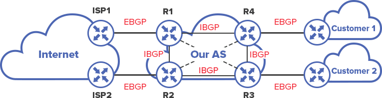
In this topology we will have two service providers (Customer 1,2) who have thier own ASN. Each customer has connectivity to a single ISP (ISP1,2.) In order for one customer to reach the other packets must be routed over eBGP - hence traversing ISP 1 and 2's ASN over BGP.


So we'll start by configuring eBGP between R2 (ASN 100) and R3 (ASN 100):

R3>
enable
conf t
int e0/1
ip address 10.254.0.1 255.255.255.252
no shutdown

router bgp 200
neighbor 10.254.0.2 remote-as 100

R2>
enable
conf t
int e0/1
ip address 10.254.0.2 255.255.255.252
no shutdown

router bgp 100
neighbor 10.254.0.1 remote-as 200

We should see an adjacancy alert appear after a little while e.g.:

*Mar  1 01:10:27.875: %BGP-5-ADJCHANGE: neighbor 10.254.0.1 Up

We can confirm our neighbors with:

show ip bgp summary

We now want to advertise our public network (13.0.0.0/24) to ISP 1 (ASN 100) - so we do this on R3 using the 'network' command:

R3>
router bgp 200
network 13.0.0.0 mask 255.555.255.0
do wri mem

We will now setup iBGP between R2 and R1 so that routes can be distributed to ASN 400 / R5:

Note: We will use a loopback address since we commonly have multiple paths to other iBGP peers - the advantage of this is if there are multiple paths to an iBGP peer and the BGP session is established over a physical link and the link goes down (or faults) the BGP session is terminated - while if using a loopback address the BGP session will remain active (and can use the other path instead.)

OK - so how would the each router (R2 and R3) know where each loopback address resides - another IGP of course - e.g. OSPF - so we setup OSPF:

R2>
enable
conf t
int e0/0
ip address 172.30.0.1 255.255.255.252
no shutdown

interface loopback 0
ip address 1.1.1.2 255.255.255.255

router ospf 1
log-adjacency-changes
network 172.30.0.0 0.0.0.3 area 0
network 1.1.1.2 0.0.0.0 area 0
network 10.254.0.0 0.0.0.3 area 0

R1>
enable
conf t
int e0/0
ip address 172.30.0.2 255.255.255.252
no shutdown

interface loopback 0
ip address 1.1.1.1 255.255.255.255

router ospf 1
log-adjacency-changes
network 172.30.0.0 0.0.0.3 area 0
network 1.1.1.1 0.0.0.0 area 0

we should be able to see each routers corrosponding loopback interface in each routing table:

do show ip route ospf

Now we can setup iBGP:

R1>
router bgp 100
neighbor 1.1.1.2 remote-as 100
neighbor 1.1.1.2 update-source loopback 0

Note: The 'update-source' statement instructs the BGP session to be initialized from the loopback adapter address.

R2>
router bgp 100
neighbor 1.1.1.1 remote-as 100
neighbor 1.1.1.1 update-source loopback 0

We can setup eBGP between R5 (ASN 400) and R1 (ASN 100):

R1>
int e0/1
ip address 192.168.10.1 255.255.255.252
no shutdown

int e0/2
ip address 172.16.20.1 255.255.255.0
no shutdown

router bgp 100
neighbor 192.168.10.2 remote-as 400
network 172.16.20.0 mask 255.255.255.0

R5>
int e0/0
ip address 192.168.10.2 255.255.255.252
no shutdown

router bgp 400
neighbor 192.168.10.1 remote-as 100

Now we want to ensure that the 13.0.0.0 network is accessable to Customer 1 (R5) - you will notice that we have to explicitly define which networks we wish to advertise to other AS's - we should firstly verify that the route is currently in our own BGP table on R1:

R1>
do show ip bgp 13.0.0.0/24

We should now be able to reach the 13.0.0.0 network from the 172.16.20.0 subnet:

do ping 13.0.0.1 source 172.16.20.1

Now we can move on to hooking up R4 and R8 to R3 with iBGP - as required by iBGP (to prevent loops) we will need to create a full mesh topology for all of our routers internally within the AS (or apply a workaround such as a route reflctor).

To do this we will start by configuring our interfaces on R3 and R4:

R3>
enable
conf t
int e0/0
ip address 172.16.0.1 255.255.255.252
no shutdown

and again we will use loopback addresses - so that the BGP session is initialized over them:

int loopback 0
ip address 3.3.3.3 255.255.255.255

router ospf 1
log-adjacency-changes
network 3.3.3.3 0.0.0.0 area 0
network 172.16.0.0 0.0.0.3 area 0

R4>
enable
conf t
int e0/0
ip address 172.16.0.2 255.255.255.252
no shutdown

int loopback 0
ip address 4.4.4.4 255.255.255.255

router ospf 1
log-adjacency-changes
network 4.4.4.4 0.0.0.0 area 0
network 172.16.0.0 0.0.0.3 area 0

We should now see the loopback interfaces within the corrosponding routing tables now.

So - lets setup iBGP:

R3>
router bgp 200
neighbor 4.4.4.4 remote-as 200
neighbor 4.4.4.4 update-source loopback 0

and on R4:

R4>
router bgp 200
neighbor 3.3.3.3 remote-as 200
neighbor 3.3.3.3 update-source loopback 0

Note: At this point I was unable to see the 17.0.0.0/24 network in the routing table - a good place to start troubleshooting is by running:

do show ip bgp 17.0.0.0/24

This will let you know whether the route has been recieved and if it is accessable - in my case I had not advertised the 10.254.0.0/30 subnet over OSPF:

R4(config)#do show ip bgp 17.0.0.0/24
BGP routing table entry for 17.0.0.0/24, version 0
Paths: (1 available, no best path)
  Not advertised to any peer
  100
    10.254.0.2 (inaccessible) from 3.3.3.3 (10.254.0.1)
      Origin IGP, metric 0, localpref 100, valid, internal

Notice the 'inaccessible' statement after the gateway.

So to resolve this we need to add the 10.254.0.0/30 into OSPF on R3:

R3>
router ospf 1
network 10.254.0.0 0.0.0.3 area 0

and recheck the routing table on R4:

do show ip route

Now we will hook up R4 to R8:

R4>
int e0/1
ip address 192.168.90.1 255.255.255.252
no shutdown

and ensure that the 192.168.90.0 subnet is advertised by OSPF:

router ospf 1
network 192.168.90.0 0.0.0.3 area 0

and on R8:

R8>
enable
conf t
int e0/0
ip address 192.168.90.2 255.255.255.252
no shutdown

int loopback 0
ip address 8.8.8.8 255.255.255.255

router ospf 1
log-adjacency-changes
network 192.168.90.0 0.0.0.3 area 0
network 8.8.8.8 0.0.0.0 area 0

and configure BGP:

router bgp 200
neighbor 4.4.4.4 remote-as 200
neighbor 4.4.4.4 update-source loopback 0

and also on R4:

R4>
router bgp 200
neighbor 8.8.8.8 remote-as 200
neighbor 8.8.8.8 update-source loopback 0

Now we review the routing table on R8 and find that there are no BGP routes! - Well we need to remember that iBGP requires a full mesh topology* and due to this we will need to hookup R8 to R3!

So on R3:

R3>
int e0/3
ip address 172.19.19.1 255.255.255.252
no shutdown

router ospf 1
network 172.19.19.0 0.0.0.3 area 0

R8>
int e0/1
ip address 172.19.19.2 255.255.255.252
no shutdown

router ospf 1
network 172.19.19.0 0.0.0.3 area 0

and then configure BGP on R3 and R8:

R3>
router bgp 200
neighbor 8.8.8.8 remote-as 200
neighbor 8.8.8.8 update-source loopback 0

R8:
router bgp 200
neighbor 3.3.3.3 remote-as 200
neighbor 3.3.3.3 update-source loopback 0

and then review R8's routing table and we should now see the BGP routes!

At the moment we have not separated our OSPF domain up - for example we don't want to have ASN 100 and 200 part of the same OSPF domain / part of Area 0 - so if I wanted I could ping a link interface of another router within another AS - although in this scenerio we only want to be able want to provide access to public IP space to Customer A and Customer B. So we will configure passive interfaces on R2 (e0/1), R3 (e0/1), R1 (e0/1) and R4 (XXXXXXXXXXXXXXXXXXXXXXXXXXX??):

R1>
ip ospf 1
passive-interface e0/1

R2>
ip ospf 1
passive-interface e0/1

R3>
ip ospf 1
passive-interface e0/1

R4>
ip ospf 1
passive-interface e0/2

This means that we will now need to ping our BGP advertised networks from another BGP advertised network i.e. you won't be able to ping a public address from a local p2p link - so for example if we wanted to access the 17.0.0.0/24 subnet from the 13.0.0.0/24 subnet we would do as follows:

R3>
do ping 17.0.0.1 source 13.0.0.1

The last step is to hook up R8 (AS 200) to R7 (AS 300) - although for AS 300 we will be injecting a default route from BGP into the IGP (OSPF.)

R4>
enable
conf t
int e0/2
ip address 192.168.245.1 255.255.255.252
no shutdown

router bgp 200
neighbor 192.168.245.2 remote-as 300

(we also need to advertise the new network (192.168.254.0/30) to our OSPF neighbors so that they can access the next hop (192.168.245.2) for the route.

router ospf 1
network 192.168.245.0 0.0.0.3

R7>
enable
conf t
int e0/2
ip address 192.168.245.2 255.255.255.252
no shutdown

router bgp 300
neighbor 192.168.245.1 remote-as 200

Monday 10 October 2016

firewalld / firewall-cmd quick start

We should firstly ensure that the service is running with:

firewall-cmd --state

We want to ensure any newly added interfaces will automatically be blocked before we explicitly define who can access them:

firewall-cmd --set-default-zone=block

and then configure our interface zones:

firewall-cmd --permanent --zone=public --change-interface=eno333333
firewall-cmd --permanent --zone=internal --change-interface=eno222222

We must also define the 'ZONE' variable within our interface config:

vi /etc/sysconfig/network-scripts/ifcfg-eno333333

and append:

ZONE=public

Restart the network service and ensure the firewall is reloaded:

sudo service network restart
firewall-cmd --reload

To review we can issue the following to take a look at any active zones:

firewall-cmd --get-active-zones

We will want to setup SSH access:

firewall-cmd --zone=internal --add-service=ssh --permanent
firewall-cmd --zone=public --add-service=https --permanent

and ensure the we define a source:

firewall-cmd --zone=public --add-source=0.0.0.0/0 --permanent
firewall-cmd --zone=internal --add-source=10.0.0.0/24 --permanent

if we want to lock down different sources to different ports (for example if you are using a single interface) - we could issue a 'rich rule' with provide us with more granualr control over sources / service relations:

firewall-cmd --permanent --zone=public --add-rich-rule='rule family="ipv4" source address="0.0.0.0/0" port protocol="tcp" port="443" accept'
firewall-cmd --permanent --zone=public --add-rich-rule='rule family="ipv4" source address="10.0.0.0/24" port protocol="tcp" port="ssh" accept'

And to review rules within zone we issue:

firewall-cmd --permanent --zone=public --list-all
firewall-cmd --permanent --zone=internal --list-all

and reload the firewall to ensure changes are applied:

firewall-cmd --reload

Friday 7 October 2016

iBGP: Full mesh requirement

When implementing iBGP in your AS you are required to create a full mesh topology - that is - all routers need to be logically connected to every other device in the AS via a neighbor peer relationship - hence requiring you setup individual peering sessions between them all.

The reasoning behind this while eBGP (or when routing between AS's) uses the AS_PATH field to avoid loops - by rejecting an advertised route if the AS_PATH contains it's own AS number, iBGP does not modify this field and hence can't detect loops. For example:

Lets say we have three routers A, B and C - all within a single AS and a eBGP router. The eBGP router then advertises a prefix to router A, which in turn installs it and then advertises it to router B, installs it and then advertises it to router C, installs it and then advertises it to router A - now if router A accepts the route it will cause a loop - now since the AS_PATH is not modified Router A is unsure whether it is a new route advertisement or it is simply an advertisement that has already traversed the router and is being sent back.

Although as your network become larger this can present serious scalability issues - so to combat this we can utilize either route reflectors or confederations.

Route Reflectors: Allow you to avoid having to have a full mesh topology between all of your BGP speakers, instead a cluster is formed where the BGP speakers form a session with the route reflector node - which in turn learns all routes and then advertises them to the BGP speakers. This does however introduce a single point of failure - so utilizing multiple RR's is generally good practice.

Confederations: A confederation is simply another internal AS that is used to split up the existing internal AS - that in turn then hooks up to the eBGP AS.

Typically is it good practise to establish the iBGP sesion using a loopback interface since the interface will remain up dispite any physical faults with a port going down..

Sources:

https://www.juniper.net/documentation/en_US/junos13.3/topics/concept/bgp-ibgp-understanding.html

BGP (Border Gateway Protocol) Summary

(e)BGP is a type of EGP (Exterior Gateway Protocol) - in fact the only one in use today and is used to provide roouting information accross the internet (across AS's.) opposed to an IGP (Interior Gateway Protocol) such as EIGRP or OSPF that provides routing information accross nodes in a single AS (Aoutonomous System.)

One of the fundamental differences between BGP and other routing procotols such as EIGRP, OSP etc. is that both parties (routers) must explicitly define a membership with each other.

There is also another type of BGP called iBGP - that as the name suggests is used

iBGP and eBGP both make use of AS (Autonomous System) numbers. Currently AS numbers are defined a 16-bit hence allowing a maximum of 65535 ASN's - although there are proposals for this to be raised to 16bit: https://tools.ietf.org/html/rfc6793

AS Numbers 1 - 64,495 are used for public use (eBGP) and 64,512 to 65,534 are reserved for private use (iBGP.)

The vast majority of publically (eBGP) available AS's are assigned to either ISPs and large enterprises. Although private AS's (iBGP) is typically applied within large ISP networks.

Typically we are used to routing protocols focussing on finding the optimal path to all destinations - although BGP differs somewhat as peering agreements between different ISPs can be very complex and as a result BGP carries a large number of attributes (metrics) with each IP prefix.

Some of the more commonly used are:

AS Path: The complete path outlining exactly which autonomous systems a packet would have to traverse to get to its destination.

Local Preference: Used in iBGP - if in the event there are multiple paths from one AS to another this attribute defines the preferred path.

Communities: This attribute is appended to a route being advertised to a nieghbor BGP router that provides specific instructions such as:

No-Advertise: Don't advertise the prefix to any BGP neighbors
No-Export: Don't advertise the prefix to any eBGP neighbors

BGP was built for security and scale-ability - although is certainly not the fastest routing protocol when dealing with convergence - hence internal routing is performed by a protocol with faster convergence such as OSPF and then external / internet routes are exchanged by BGP.


The diagram above shows a good (yet simplistic) representation of a service provider - we are firstly assigned our public ASN - we have a core network running iBGP between our core routers. We are also peering with two ISPs (i.e. we form an adjacency with their routers over eGBP) and also have two customers who use eBGP to peer with our network.

As a good introduction to BGP I would also highly reccomend taking a look at an article by the Internet Society.


Wednesday 5 October 2016

Setting up JunOS 12.1 (Olive) with GNS3

For this setup I am presuming you have already installed GNS3.

We will need to firstly ensure VirtualBox (https://www.virtualbox.org/wiki/Downloads) is installed and that you have downloaded the JunOS virtual appliance:

https://drive.google.com/open?id=0BzJE2w8IRXVvX0U1Y0lSdndMWVk

Note: The above you not be used for commercial purposes at all - as well as being outdated, it is not supported at all by Juniper and should be used for developmental and testing purposes only.

From VirtualBox we do a: File >> Import Appliance, specifying our ova image.

It is also worth ensuring that the NIC attached to the VM is in bridging mode:

VM >> Properties >> Network.

and adding 1 or 2 extra interfaces - since by default it only provisioned one in my testing.

Note: The VM might take a little while to initialize on lower end systems, so be patient.

At the login prompt we can simply login with root (no password.)

and verify the JunOS version with:

show version brief

We should then promptly set the root password:

conf
set system root-authentication plain-text-password
set system host-name JUNOS

and then we can configure the em0 interface with:

set interface em0 unit 0 family inet address 10.0.0.100/30
commit

We should be able to verify this with:

run show interfaces em0 detail

and then attempt to ping your default gateway to verify connectivity:

run ping 10.0.0.1

We should now hook up Virtualbox with GNS3 by firstly pointing it to our VBoxManage executable:

GNS3 >> Edit >> Preferences >> VirtualBox >> 'Path to VBoxManage'.

Note: This will typically be: C:\Program Files\Oracle\VirtualBox\VBoxManage.exe

Then hit the 'VirtualBox VMs' tab and add our newly created VM.

You should then see the VM (JunOS Olive) available 'End Devices' tab within GNS3.

Route redistribution with OSPF and EIGRP

Route redistribution is simply the process of sharing information between two or more routing protocols - since by design OSPF and EIGRP (RIP etc.) are not compatible with each other - for example ODPF uses cost as a metric, while EIGRP uses K-Values.

For this lab we will be redistributing routing information across a EIGRP and OSPF domain - we will be using the previous lab here as a starting point.


With the addition of a EIGRP domain of which we want to redistribute information accross the OSPF and EIGRP domain:

R2>
int e0/1
ip address 172.16.30.1 255.255.255.252
no shutdown
ip ospf 1 area 0

router ospf 1
network 172.16.30.0 0.0.0.3 area 0


R3>
enable
conf t
int e0/1
ip address 10.1.0.1 255.255.255.252
no shutdown

int e0/0
ip address 172.16.30.2 255.255.255.252
no shutdown
ip ospf 1 area 0

we will create a new EIGRP AS:

router eigrp 10
no auto-summary
network 10.1.0.0 0.0.0.3

router ospf 1
router-id 3.3.3.3
network 172.16.30.0 0.0.0.3 area 0

R4>
enable
conf t
int e0/0
ip address 10.1.0.2 255.255.255.252
no shutdown

int e0/1
ip address 10.16.32.1 255.255.255.0
no shutdown

router eigrp 10
no auto-summary
network 10.1.0.0 0.0.0.3
network 10.16.32.0 0.0.0.255

We should now see a new adjacency form - confirm with:

do show ip eigrp ne

Now we need to perform the redistribution - one important thing to remember about route redistribution is that it is an outbound process for example in our topology

Since different routing protocols use different metrics we will need to convert the metric from one protocol to one that supports the destination routiong protocol - for example:

Redistribution into RIP requires the seed metric of 'Infinity.'
Redistribution into EIGRP requires the seed metric of 'Infinity.'
Redistribution into OSPF requires the seed metric of '20' or '1' if originating from BGP.
Redistribution into BGP requires the IGP metric.

Because we want to distribute our routes into our EIGRP domain we also need to ensure we have set our default K-Values as the routes will not show up without this information firstly defined:

R3>
router eigrp 10
default-metric 1500 100 255 1 1500
redistribute ospf 1 metric 1544 2000 255 1 1500

and then the other way  - redistributing OSPF routes into EIGRP:
router ospf 1
redistribute eigrp 10 metric 50000 subnets

We can then hop onto R2 and check the routes - you will notice something like the following:

O E2    10.1.0.0/30 [110/50000] via 172.16.30.2, 00:02:19, Ethernet0/1
O E2    10.16.32.0/24 [110/50000] via 172.16.30.2, 00:02:19, Ethernet0/1

Note: The E2 indicates that the network is resides outside the OSPF domain - that is - within our EIGRP domain.

And again on R4 we should see something like:

D EX    172.16.30.0 [170/2195456] via 10.1.0.1, 00:05:07, Ethernet0/0
     10.0.0.0/8 is variably subnetted, 3 subnets, 2 masks
D EX    10.0.0.0/30 [170/2195456] via 10.1.0.1, 00:05:07, Ethernet0/0

Tuesday 4 October 2016

OSPF Route Summarization

Route summarization - as the name suggests allows you to summarize a group of networks - by specifying a single prefix - for example if we had the following subnets:

192.168.0.0/24
192.168.1.0/24
192.168.2.0/24
192.168.3.0/24

we could summarize them as:

192.168.0.0/22

Route summarization in OSPF can only be performed on the ABR or ASBR - this is because the LSDB (Link State Database) must be exactly the same on all routers within the area.

Note: It is only possible to summarize LSA type 3 (for inter-area routers) and type 5 (external networks that are redistributed into OSPF.)

While route summarization can be useful since it helps reduce the number of routes present in the routing table - it is not enabled by default and must be manually configured.

Another advantage of route summarization is that if we have summarized the above routes as 192.168.0.0/22 and the link to 192.168.2.0/24 goes down - we will not have to change our routing table (no flooding of LSA's needed) and hence save computation power for performing the SPF algorithm of each router and of course bandwidth.

For this example we will have a simple topology - two routers - R1 acting as the DR in Area 0 and R2 acting as an ABR in Area 0 and 1:


Firstly we shall setup the basic OSPF configuration:

R1>
enable
conf t
int e0/0
ip address 10.0.0.1 255.255.255.252
no shutdown
ip ospf 1 area 0

router ospf 1
router-id 1.1.1.1
network 10.0.0.0 0.0.0.3 area 0

R2>
enable
conf t
int e0/0
ip address 10.0.0.2 255.255.255.252
no shutdown
ip ospf area 0

router ospf 1
router-id 2.2.2.2
network 10.0.0.0 0.0.0.3 area 0

Now the adjacency has formed we will add several loopback adapters (which we will summarize) e.g.:

R2>
int loopback 1
ip address 192.168.0.1 255.255.255.255

int loopback 2
ip address 192.168.1.1 255.255.255.255

int loopback 3
ip address 192.168.2.1 255.255.255.255

int loopback 4
ip address 192.168.3.1 255.255.255.255

router ospf 1
network 192.168.0.1 0.0.0.0 area 1
network 192.168.1.1 0.0.0.0 area 1
network 192.168.2.1 0.0.0.0 area 1
network 192.168.3.1 0.0.0.0 area 1

Wait for the changes to propagate and then check the routing table on R1:

do show ip route

Now we will firstly perform Type 3 summarization - i.e. intera-area summarization - this is performed on the ABR (R2 in our case) using the 'range' keyword:

R2>
router ospf 1
area 1 range 192.168.0.0 255.255.255.0
end
wri mem

Then on R1 we can verify that the summarized route is present with:

do show ip route

Now as stated earlier we can also summarize Type 5 (External) LSA's - this can be performed when cooked up to another routing protocol such as EIGRP - on the ASBR we simply need to identify the routes we wish to summarize:

show ip ospf database | begin Type-5

and use the 'summary-address' command:

conf t
router ospf 1
summary-address 172.16.0.0 255.255.0.0

Route Filtering with OSPF

Route filtering allows us to prevent routes from being distributed between other routers in our domain / area.


One important thing to note about OSPF is that normal routers within thier area are unaware of where inter-networks reside (the other areas topology ) in that area and instead simply reference the area's ABR - i.e. for example in the topology above if we look at the Router1's OSPF database:

do show ip ospf database

...
            OSPF Router with ID (1.1.1.1) (Process ID 1)

                Router Link States (Area 0)

Link ID         ADV Router      Age         Seq#       Checksum Link count
1.1.1.1         1.1.1.1         1311        0x80000008 0x009b17 2
2.2.2.2         2.2.2.2         1402        0x80000007 0x00e813 2
3.3.3.3         3.3.3.3         1358        0x80000002 0x000123 1

                Net Link States (Area 0)
Link ID         ADV Router      Age         Seq#       Checksum
10.0.0.2        2.2.2.2         1310        0x80000004 0x003acd

                Summary Net Link States (Area 0)
Link ID         ADV Router      Age         Seq#       Checksum
10.1.0.0        3.3.3.3         1358        0x80000003 0x0094b3
192.168.1.0     3.3.3.3         1338        0x80000004 0x00766e
10.1.0.0        2.2.2.2         1072        0x80000003 0x00b299
10.2.0.0        3.3.3.3         1050        0x80000005 0x0084c0
192.168.3.0     3.3.3.3         364         0x80000008 0x00627b

We can see that the 192.168.3.0/24 (attached to Router4) network we can see that the advertising router is 3.3.3.3 (Router3) - where in fact it was originally advertised by Router 4 (4.4.4.4.)

Since unlike distance vector protocol such as RIP and EIGRP; OSPF uses LSA's to distribute routes - although if we filter LSA's with an area we will come into problems - since the Link State Database of the routers within an area MUST be the same - so instead we can filter routes from entering into the routing table - however it is possible to filter LSA's between areas (ABR's) or between routing domains (ASBR's) though.

For this example we want to ensure the 192.168.3.0 network is not present in Router1's routing table - we accomplish this with a prefix list on Router1 (Area 0):

Router1>
ip prefix-list netblock seq 10 deny 192.168.3.0/24
ip prefix-list netblock seq 20 allow 0.0.0.0/0

router ospf 1
area 0 filter-list prefix netblock in
do wri mem

We can then review the absense of the route from the routing table with:

show ip route ospf

Although notice it is still present in the link state database:

show ip ospf database

Monday 3 October 2016

Setting up OSPF Virtual Links

When setting up OSPF it is required that all areas (i.e. ABRs) are connected to the backbone area (0) - in some more complex topologies there might be (planned) areas that do not have a direct link to the backbone area - this is where virtual links come into play - they provide a way for these areas to tunnel through an adjacent area to the backbone area.


In the (simplified) diagram above we can clearly see that although Area 1 has a direct connection to Area 0, Area 2 does not and due to this we will need to create a virtual link.

We should firstly setup OSPF on all three routers:-

Router1>
enable
conf t
hostname Router1

int g0/0
ip address 10.0.0.1 255.255.255.252
no shutdown
ip ospf 1 area 0

int g0/1
ip address 192.168.2.1 255.255.255.0
no shutdown
ip ospf 1 area 0


router ospf 1
router-id 1.1.1.1
network 10.0.0.0 0.0.0.3 area 0
network 192.168.2.0 0.0.0.255 area 0

do wri mem

Router2>
enable
conf t
hostname Router2

int g0/0
ip address 10.0.0.2 255.255.255.252
no shutdown
ip ospf 1 area 0

int g0/1
ip address 10.1.0.1 255.255.255.252
no shutdown
ip ospf 1 area 1

router ospf 1
router-id 2.2.2.2
network 10.1.0.0 0.0.0.3 area 1
network 10.0.0.0 0.0.0.3 area 0

do wri mem

Router3>
enable
conf t
hostname Router3

int g0/0
ip address 10.1.0.2 255.255.255.252
no shutdown
ip ospf 1 area 1

int gi0/1
ip address 192.168.1.1 255.255.255.0
no shutdown
ip ospf 1 area 2

router ospf 1
router-id 3.3.3.3
network 10.1.0.0 0.0.0.3 area 1
network 192.168.1.0 0.0.0.255 area 2

do clear ip ospf pro
do wri mem

At this point you will notice that all routers will be able to see networks within Area 1 and 0 - although as Area 2 has no direct link to Area 0 the networks within this area will not be visible within Router 2 and Router 1's routing table (i.e. the 192.168.1.0/24 network in this case.)

This is where virual links come into play - so for this example we would create the virtual link in Area 1 since this is the intermidatry area between Area 0 and Area 2. Router2 points to Router3 (note we use the router-id and not the router IP address) and visa versa:

Router2>
conf t
router ospf 1
area 1 virtual-link 3.3.3.3

Router3>
conf t
router ospf 1
area 1 virtual-link 2.2.2.2

We should then see something like:

%OSPF-5-ADJCHG: Process 1, Nbr 2.2.2.2 on OSPF_VL0 from LOADING to FULL, Loading Done

Which simply indicates that a new adjacancy has been formed with Area 0 over our virtual link: OSPF_VL0.

We can also confirm the status of the virtual like with:

do show ip ospf virt

Now the new adjacancy has been formed we should now be able to see the 192.168.1.0/24 route in our routers OSPF database / routing table:

do show ip route

Distance Vector, Link State, Split horizon and Poison Reverse Explained

Distance Vector routing boils down to two factors - the distance (metric) of the destination and the vector (direction it takes to get there.)

Unlike link-state routing; distance vector only exchanges routing information between it's directly connected neighbors. This means that although a router knows who from whom a router was learnt - it does not know where the neighbor learnt that route from - this means that the router itself will not have a hierarchical view of other subnets and only knows which link / neighbor to use to get to that network.

Examples of routing protocols that employ distance vector routing are RIP and EIGRP (although EIGRP uses Bandwidth, Load, Delay, Reliability and MTU as a metric - AKA K-Values unlike RIP.)

The routing protocols above (by default) employ measures such as split horizon and posion reverse to prevent routing loops.

Link-state routing takes a slightly different approach in that it as aware of the complete OSPF network topology - i.e. it can see a hierarchical view of all of the routers / networks and can see which networks are attached to which routers - but obviously this can become a problem in larger OSPF domains as this might cause performance problems on low spec routers (areas are used to help manage this problem / risk.)

OSPF employs the SPF (shortest path first) algorithm in which it creates a SPF tree with itself as the root node for all known routes.

Link state advertisements (LSAs) are flooded throughout the link-state domain to ensure that all routers in the domain have an up to date copy of area's link state database.

Split horizon is a mechanism that prevents a router from advertising a route back onto the interface it originally received it from - hence preventing a routing loop - routing protocols such as RIP and EIGRP utilize this.

Poison reverse is a mechanism in which a gateway node (a node directly connected to a network) instructs it's directly connected neighbors that the link is down / network is unavailable. In order to perform this the gateway node sets the number of hops to the unavailable network to an 'infinite' amount of hops - hence other nodes in the domain then know that the network is unavailable.